This manual provides a comprehensive guide to understanding and utilizing the Shark Navigator Lift-Away Vacuum, ensuring optimal performance and maintenance for a cleaner, healthier home environment.
Overview of the Shark Navigator Lift-Away Vacuum
The Shark Navigator Lift-Away Vacuum is a versatile and functional cleaning solution designed for various surfaces and cleaning needs. Introduced in 2011, it has become a popular choice for its affordability and effectiveness; The vacuum features a detachable pod, allowing users to switch between upright and portable modes effortlessly. Its design includes advanced filtration systems and adjustable suction power, making it suitable for carpets, hard floors, and pet hair. The Lift-Away technology enables easy maneuverability and thorough cleaning of hard-to-reach areas; With its durable build and user-friendly controls, this vacuum offers a reliable and efficient cleaning experience. It is widely praised for its value and performance, making it a top choice for many households.
Importance of Reading the Manual
Reading the Shark Navigator Lift-Away Vacuum manual is essential for maximizing its performance and ensuring safe operation. The manual provides detailed instructions for assembly, operation, and maintenance, helping users understand the vacuum’s features and capabilities. It highlights safety precautions, proper usage guidelines, and troubleshooting tips to prevent damage and extend the product’s lifespan. By following the manual, users can optimize cleaning efficiency and avoid common issues. Additionally, it covers warranty information and maintenance schedules, ensuring the vacuum remains in top condition. Taking the time to read the manual guarantees a better understanding of the device, enabling users to utilize its advanced features effectively and maintain a cleaner, healthier home environment.

Key Features and Benefits of the Shark Navigator Lift-Away
The Shark Navigator Lift-Away offers versatility with its detachable pod, advanced filtration, and adjustable suction power, making it ideal for multi-surface cleaning and pet hair removal efficiently.
Design and Build Quality

The Shark Navigator Lift-Away Vacuum features a sleek, ergonomic design with durable materials, ensuring long-lasting performance. Its lightweight construction makes it easy to maneuver, while the detachable pod enhances versatility. The vacuum’s build quality is robust, with a focus on user comfort and accessibility. The curvy, modern aesthetic appeals to a wide range of users, and its compact design allows for easy storage. The use of high-quality plastics and metal components ensures reliability and durability, making it a reliable choice for daily cleaning tasks. The overall design emphasizes functionality, combining practicality with a visually appealing structure that suits various home environments.
Versatility in Cleaning Modes
The Shark Navigator Lift-Away Vacuum excels in adaptability, offering multiple cleaning modes to suit various needs. Its upright mode is ideal for carpets and hard floors, while the Lift-Away feature allows for portable, above-floor cleaning. This versatility enables users to tackle stairs, upholstery, and tight spaces effortlessly. The vacuum also comes with specialized attachments, such as the pet hair tool, enhancing its ability to handle specific tasks. Whether it’s deep carpet cleaning or dusting surfaces, the Shark Navigator’s adjustable settings and detachable design make it a versatile solution for maintaining a clean and organized home environment. Its flexibility ensures efficient cleaning across different surfaces and areas, catering to diverse household requirements.
Cost-Effectiveness and Value for Money
The Shark Navigator Lift-Away Vacuum offers exceptional value for its price, combining high-quality performance with affordability. As a functional and budget-friendly option, it has earned recognition for its cost-effectiveness, making it a top choice for households seeking reliable cleaning solutions. Introduced in 2011, the NV352 model remains popular due to its balance of performance and price. The vacuum’s versatility in cleaning modes and durable design ensure long-term savings, as it adapts to various cleaning tasks without compromising on efficiency. This makes it a practical investment for homeowners looking to maintain a clean environment without overspending. Its affordability and robust features ensure it delivers outstanding value for money, catering to diverse cleaning needs effectively.
Assembly and Setup Instructions
Begin by unboxing and inventorying all parts, then attach the Lift-Away pod securely. Follow the manual’s step-by-step guide to assemble and prepare the vacuum for its first use.
Unboxing and Inventory of Parts

When you unbox your Shark Navigator Lift-Away Vacuum, carefully inspect and organize all components. Typically, the package includes the main vacuum unit, the detachable Lift-Away pod, a wand, crevice tool, upholstery tool, and the dust cup. Ensure no parts are missing by cross-referencing with the manual’s inventory list. Familiarize yourself with each accessory’s purpose, such as the crevice tool for tight spaces or the upholstery tool for furniture. If any items are damaged or missing, contact customer support immediately. Properly organizing these parts will streamline your cleaning experience and ensure everything is within reach when needed. Always refer to the manual for clarification on any component.

Attaching the Lift-Away Pod
Attaching the Lift-Away pod to your Shark Navigator vacuum is a straightforward process. First, ensure the pod is aligned with the vacuum’s base. Locate the release button on the pod’s handle and press it to detach any existing attachments. Next, slide the pod onto the vacuum’s base until it clicks securely into place. Make sure the pod is properly aligned to avoid any obstructions. Once attached, test the connection by gently tugging on the pod to ensure it is stable. Proper attachment ensures smooth operation and prevents accidental detachment during use. Always refer to the manual for visual guidance if needed.
Setting Up the Vacuum for First Use
Setting up your Shark Navigator Lift-Away Vacuum for the first time is an exciting step toward achieving a cleaner home. Begin by carefully unboxing and inventorying all parts to ensure nothing is missing. Next, attach the Lift-Away pod to the upright base by aligning the connectors and securing it with a gentle click. Inspect the vacuum for any damage or debris from shipping. Charge the battery (if applicable) for the recommended time before first use. Finally, familiarize yourself with the controls and settings, such as suction power adjustment and mode selection. Proper setup ensures optimal performance and longevity of your vacuum.
Operating the Shark Navigator Lift-Away Vacuum
Operating the Shark Navigator Lift-Away Vacuum is straightforward, with intuitive controls and versatile modes that make cleaning effortless across various surfaces, ensuring a seamless and efficient cleaning experience.
Basic Operation and Controls
Operating the Shark Navigator Lift-Away Vacuum is simple and intuitive. The vacuum features a user-friendly control panel with clear buttons for power, suction adjustment, and mode selection. To start, plug in the device and press the power button. Use the suction control slider to adjust power based on the surface type, ensuring optimal cleaning without damaging delicate areas. The ergonomic handle provides comfortable grip and easy maneuverability. For upright mode, simply push the vacuum forward, and for Lift-Away mode, detach the pod for handheld cleaning. Always ensure the dust cup is empty and filters are clean for maximum performance. Refer to the manual for detailed guidance on specific settings and maintenance tips to prolong the vacuum’s lifespan and efficiency.
Using the Upright Mode
The upright mode of the Shark Navigator Lift-Away Vacuum is ideal for cleaning large areas with ease. To use this mode, ensure the vacuum is fully assembled and the Lift-Away pod is securely attached. Press the power button located on the handle to turn it on. Use the suction control slider to adjust the power based on the surface type, such as carpets, rugs, or hard floors. The ergonomic handle allows for comfortable maneuverability, enabling smooth gliding across surfaces. For optimal performance, empty the dust cup regularly and ensure the pre-filter and post-filter are clean. This mode is perfect for deep cleaning carpets and tackling pet hair with minimal effort, making it a versatile option for everyday cleaning tasks.
Switching to Lift-Away Mode
To switch to Lift-Away mode, press the release button located on the side of the vacuum pod. This detaches the pod from the upright section, allowing for portable cleaning. Once detached, attach the desired cleaning tool, such as the crevice tool or upholstery brush, to the end of the pod. This mode is ideal for cleaning stairs, furniture, and hard-to-reach areas. The lightweight design makes it easy to maneuver without strain. Always ensure the pod is securely reattached when returning to upright mode to maintain balance and stability; Regularly check the connections to ensure proper functionality and avoid accidental detachment during use. This feature enhances versatility, making the Shark Navigator Lift-Away a multi-functional cleaning solution for various surfaces and spaces.
Adjusting Suction Power
The Shark Navigator Lift-Away Vacuum allows users to adjust suction power based on cleaning needs. Locate the suction control slider, typically found on the handle or vacuum pod. Slide it to increase or decrease power for different surfaces. Higher suction is ideal for thick carpets, while lower settings work best for delicate floors or curtains. This feature ensures efficient cleaning without damaging surfaces. Regularly check and adjust the suction to optimize performance for various tasks. Proper adjustment enhances cleaning effectiveness and prolongs the vacuum’s lifespan. Always refer to the manual for specific guidance on suction control for different attachments and modes. This versatility makes the Shark Navigator Lift-Away a practical choice for diverse cleaning requirements. Adjusting suction power is a simple yet effective way to customize your cleaning experience.

Maintenance and Troubleshooting
Regular maintenance ensures optimal performance. Clean or replace filters, empty the dust cup, and check for blockages. Address common issues promptly to maintain efficiency and longevity.
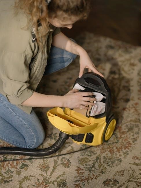
Cleaning and Replacing the Filter
Regular filter maintenance is crucial for optimal performance. The Shark Navigator Lift-Away Vacuum’s filter should be cleaned every 1-2 months. To clean, remove the filter, rinse it under cold water until the water runs clear, and allow it to air dry completely. Avoid using detergent, as it may damage the filter. Once dry, reinstall the filter to ensure proper suction power. If the filter is damaged or shows signs of wear, replace it immediately. A clean filter improves air quality and suction efficiency, while a clogged or dirty one can reduce performance. Always refer to the manual for specific instructions on your model’s filter maintenance.
Emptying the Dust Cup
To maintain optimal performance, empty the dust cup after each use. Press the release button located on the handle or canister to detach the cup. Hold it over a trash can, open the bottom lid, and allow the debris to fall out. For stubborn particles, gently tap the cup or rinse it with cold water. Ensure the lid is securely closed before reattaching. Regular emptying prevents dust buildup and maintains suction power. For best results, wash the dust cup with mild soap and water monthly, allowing it to dry completely before reuse. This simple step ensures your vacuum operates efficiently and effectively, keeping your home clean and dust-free.
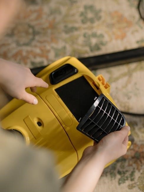
Checking for Blockages
Regularly inspecting your Shark Navigator Lift-Away Vacuum for blockages ensures optimal performance. Start by detaching the Lift-Away pod and examining the pre-filter for debris. Check the hose, wand, and vacuum inlet for obstructions. If you notice a loss of suction, remove any blockages by gently cleaning or replacing the affected parts. For stubborn clogs, use a soft brush or a small tool to clear the pathway. Always ensure all components are securely reattached after cleaning. By maintaining a blockage-free system, you preserve the vacuum’s efficiency and extend its lifespan. This simple maintenance step is crucial for consistent cleaning results and overall functionality.
Common Issues and Solutions
Common issues with the Shark Navigator Lift-Away Vacuum often relate to suction power and blockages. If the vacuum loses suction, check the dust cup for fullness and empty it if necessary. Ensure the pre-filter and post-filter are clean or replaced as needed. For clogs, inspect the hose, wand, and vacuum inlet for obstructions and clear them. If the vacuum is difficult to maneuver, adjust the suction control dial to reduce power for lighter cleaning tasks. Additionally, ensure all connections are secure, as loose parts can disrupt performance. Regular maintenance, such as cleaning filters and checking for blockages, helps prevent these issues and maintains the vacuum’s efficiency. Addressing these common problems ensures optimal performance and extends the product’s lifespan.
Advanced Features and Settings

The Shark Navigator Lift-Away features advanced filtration systems, capturing 99.9% of dust and allergens, and includes specialized tools like the Pet Hair Tool for efficient cleaning.
Using the Pet Hair Tool
The Pet Hair Tool is a specialized attachment designed to tackle stubborn pet hair on upholstery, stairs, and other surfaces. To use it effectively, attach the tool to the wand or directly to the Lift-Away pod. Gently glide it over the affected areas, using light pressure for optimal results. The tool’s unique design captures pet dander and allergens, ensuring a deeper clean. For best performance, clean the tool regularly by removing accumulated hair and washing it with mild soap. This attachment is a must-have for pet owners, making quick work of pet hair cleanup and maintaining your home’s freshness and hygiene;
Advanced Filtration Systems
The Shark Navigator Lift-Away Vacuum features an advanced filtration system designed to capture dust, allergens, and pet dander effectively. The vacuum includes a HEPA filter, which traps 99.97% of particles as small as 0.3 microns, making it ideal for households with allergies. Additionally, a pre-filter captures larger debris, extending the life of the HEPA filter. Regular cleaning and replacement of these filters ensure optimal performance and air quality. The system is also designed to reduce odors, leaving your home smelling fresh. Proper maintenance of the filters is essential to maintain suction power and filtration efficiency, ensuring your vacuum continues to deliver exceptional cleaning results over time.

Comparing with Other Shark Navigator Models
The Shark Navigator Lift-Away stands out among other models like the NV352 and NV600, offering enhanced features, improved design, and advanced filtration for superior cleaning performance and versatility.
Differences Between NV352 and NV600 Models
The NV352, introduced in 2011, is a classic model known for its reliability and affordability, while the NV600 series, including NV600UK, offers advanced features and improved design. The NV600 models feature enhanced filtration systems, better suction power, and a more ergonomic build compared to the NV352. Additionally, the NV600 series includes models with specialized tools for pet hair and allergen trapping, making them more versatile for diverse cleaning needs. While both models share the Lift-Away functionality, the NV600 series provides a more modern and refined cleaning experience, catering to users seeking higher performance and convenience.
User Reviews and Feedback
Users praise the Shark Navigator Lift-Away Vacuum for its functionality, affordability, and versatility. Many highlight its effectiveness in pet hair cleaning and ease of use, though some note weight and battery concerns.
Pros and Cons from Real Users
Real users highlight the Shark Navigator Lift-Away Vacuum’s effectiveness in cleaning, ease of use, and versatility across different surfaces. Many appreciate its lightweight design and detachable pod for convenient cleaning. The vacuum is particularly praised for its ability to handle pet hair efficiently. However, some users note that the device can be heavy in upright mode and that the battery life could be improved. Additionally, a few mention that the dust cup capacity is smaller than expected. Despite these minor drawbacks, the majority of users agree that the Shark Navigator offers excellent value for its price, making it a reliable choice for everyday cleaning needs.
The Shark Navigator Lift-Away Vacuum Manual serves as an essential guide for maximizing the potential of this versatile cleaning tool. By following the instructions and understanding its features, users can enjoy efficient and effective cleaning across various surfaces. The vacuum’s design, affordability, and performance make it a popular choice for many households. While it may have minor drawbacks, such as weight in upright mode and smaller dust cup capacity, its overall benefits and value for money outweigh these limitations. For anyone seeking a reliable and adaptable vacuum, the Shark Navigator Lift-Away is a strong contender, backed by positive user feedback and proven performance.